


Crossfeed in a tin
![]()
![]()
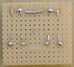
This is complimentary to the Jan Meier Bass enhanced Lite crossfeed tutorial I published here and is available to anyone who owns a soldering iron and has a couple of quid and a tin of mints kicking around. The picture quality is abysmal thanks to my 1 megapixel camera (on this occasion I blame my tools!) but I hope you find it easy to follow. It is, quite literally painting by numbers and I feel the less technobabble the easier it will be for you to construct.
Here is the parts list for the circuit but feel free to substitute them with "audiograde" parts if you feel that way inclined :-) I had a spare 2 hours to solder an x-feed together with a huge gas soldering iron (I was outdoors), take step by step pictures, write all this stuff and upload it all to this website! so please excuse the pretty shoddy soldering and the even naffer images :-) As long as you get the general assembly procedure is all that matters at the moment. The parts I list for the actual board make for a superb crossfeed.
I haven't included diagrams showing people how to drill a hole in a tin can as I feel that would be an insult on their intelligence but if you would like to see a step by step guide which includes drilling holes in a tin then let me know: Any other comments / sugestions would be appreciated.
X-Feed lite original pics tutorial
Enclosure ideas coming soon
Ingredients for the engine:
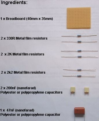
Note: a 220nF will do the job if a 200nF is hard to find. (I think 220nf
sounds "better")
![]()
![]()
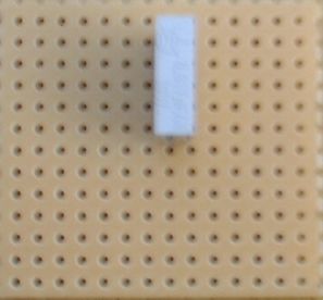
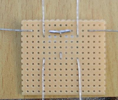
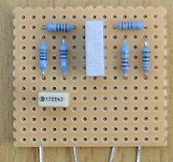
Fit the 47nf capacitor
![]()

![]()
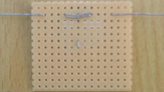
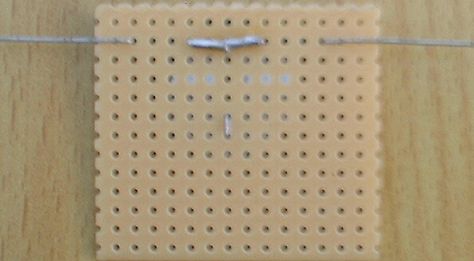
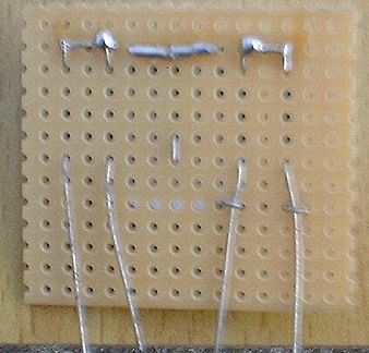
Turn the board over and bend the legs of the 47nf capacitor over as shown
![]()

![]()
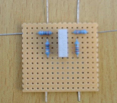
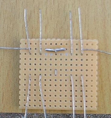
Fit the 2 x 2k2 resistors and bend the legs over on the underside of the board
![]()
![]()
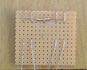
Bend the leg of the 47nf capacitor over the 2 legs of the resistors to provide a mechanical joint
![]()
![]()
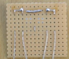
Solder the 2 legs of the 2k2 resistors and and the 47nf capacitor leg
together
(note: you are connecting one leg of each of the 2k2 resistors which
are closest to the 47nf capacitor leg)
![]()
![]()
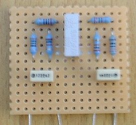
Turn the board over and fit the 2k resistors as shown
![]()
![]()
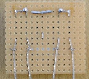
Underneath should look like this
![]()

![]()
Fit the two 330R resistors as shown
![]()
![]()
underneath should now look like this
![]()
![]()
Now connect all the resistor legs adjacent to the 47nf capacitor as shown
![]()
![]()
Solder and snip off excess legs
![]()
![]()
Fit one of the 220nF capacitors as shown
![]()
![]()
bend the legs of the 220nf capacitor over the legs of the resistors to make a mechanical joint as shown
![]()
![]()
Fit the other 220nF capacitor
![]()
![]()
Bend the legs of the 220nf capacitor over the other set of resistor legs as shown
![]()
![]()
Snip and solder
![]()
![]()
Clean the underside of the board with isopropyl alcohol and a toothbrush
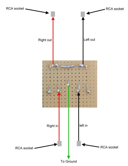
solder your hook up wire to the points shown on the underside of the board and that's you with a crossfeed unit. If you are using a metal enclosure then it is only necessary to solder the ground to one of the ground tags on the RCA sockets but if you are using a plastic enclosure then it's essential you solder all 4 RCA tags to ground to ensure continuity... this can be done by soldering one wire onto the ground of the board into a connector strip and taking the other 3 ground wires from that or you can simply ground one RCA ground tag and piggyback the rest with hook up wire...... ie: solder a wire onto one ground tag, solder a wire from it onto the next ground tag and so on and so forth.
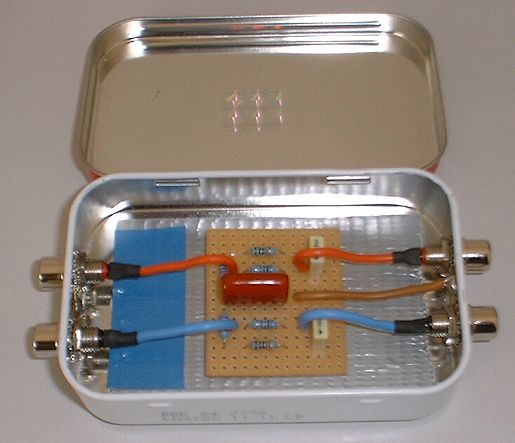
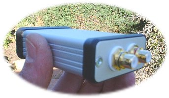
In the mint tin example you can see I have soldered both left and right ground tags together and run a hook up wire from the ground on the board to them... that's sufficient in a metal enclosure as the tin acts as a conductor. Be sure not to use the plastic washers that come with the RCA's as they insulate the ground tags from the chassis.
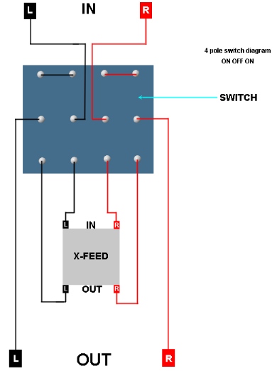
Bypassing the crossfeed with a switch

X-Feed in a Hammond